In either case the algorithm execution time is dominated by data movement and branching, not by floating-point operations. If you place two surfaces close to each other in a 3D scene, there is a risk that they start flickering, especially when the camera is positioned high above the surfaces. Additional floating- point operations are required only in the event of actual clipping, i.e. Why is your model being clipped in front of the camera 1. In a working context, being unable to provide this very basic technique comes is unprofessional. clipping plane, 6 compares per vertex in a 3D system. It takes a long time to verify this each time, with all the different settings and display possibilities contributing.

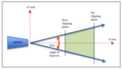
Sometimes when setting a large clipping range will allow you to see both near and far objects, but reduces the depth precision resulting in artifacts. So, the near clipping plane is at z near, and the far clipping plane is. Each time I assume that it’s because of the particular configuration I’m attempting (at the moment with objects imported from Sketchup) but it always boils down to the fact that it frequently simply doesn’t work on any object. 3D Viewport¶ Rendering¶ Depth Buffer Glitches¶. The volume of space that is actually rendered into the image is called the. Every few months I assume that it will surely work, but it never does. We consider the fragment pro-cessing of a particle of center P (xp,yp,zp. For the formal discussion of the processing of a single particle, let us use the notations of gure 4. In this approach, the color segmentation of known visual scene is carried out according to a predefined threshold, and the segmented image is processed by morphology. To solve this problem, this paper proposes a visual image rendering based on scene visual understanding algorithm.

When hatches are left off it almost always leads to confusion.Īnd yet in Rhino this has never been reliable. z front clipping plane f Zs s object particle sphere Figure 4: Computation of length 6s the ray segment travels inside a particle sphere of radius r and of center P. The rendering effect of known visual image texture is poor and the output image is not always clear. It is NOT common practice for a sectioned object NOT to have a hatch.

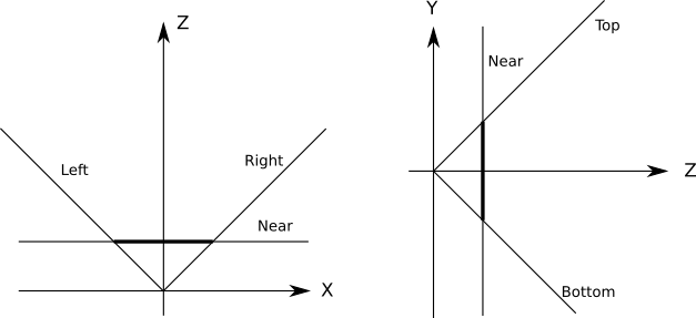
far specifies the location of the far clipping plane. Basic convention has always been that if a plan or cross section goes through an object, the interior of the object is hatched, usually in a solid tone in a design drawing, just as often with diagonal lines in a construction drawing. (left, bottom, -near) and (right, top, -near) specify the points on the near clipping plane that are mapped to the lower left and upper right corners of the window, respectively, assuming that the eye is located at (0, 0, 0). Almost no design can be communicated without a plan or cross section.


 0 kommentar(er)
